

It isn't easy knowing the difference between a master telephone socket and an extension socket, especially if you've no experience in this area.
Extension sockets are traditionally wired off the master, however, in recent years NTE5 or CTE5 Line boxes have been fitted in place of master sockets. These have a removable panel which houses the terminals to connect wiring to the secondary sockets.
In simple terms, the difference between the two is this;
A master or primary socket has three components inside that are absent in the extension socket;
These are
1) A surge suppressor across the line pins 2-5
2) A capacitor that couples the AC ringing current from one side of the line (pin 2) onto pin 3
3) A high-value resistor forming a return path from pin 3 back to the other side of the line (pin 5) so that line testing equipment can "see" a termination with nothing plugged in.


Tools You Will Need
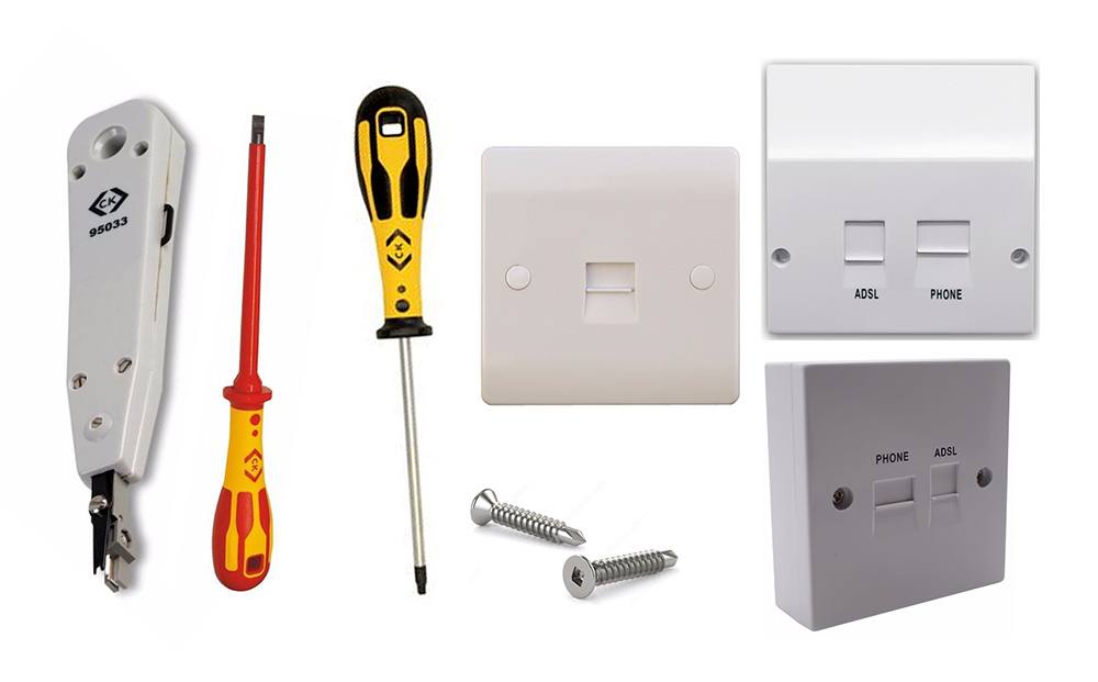
• Punch Down Stripping Tool - For fast and secure seating of data wires into terminals, automatic, precise trimming and sealing action.
• Slotted Parallel Flat Head Insulated Screwdriver - The C.K Dextro VDE Screwdriver Slotted Screwdriver, extra response, extra feel and extra speed, comfortable to work with, ergonomic design with rounded spinning area.
• Screwdriver - the C.K Tools Robertson Dextro Screwdriver is designed with professionals, by professionals; to give this screwdriver the ideal ergonomic design.
• Self Driving Wood Screws - ideal for securing your installations in place.
• Telephone Master Socket Flush Wall Switch - a master telephone socket, designed to connect your home to your service provider, not to be confused with Secondary Sockets for general use around the home.
• ADSL Broadband Faceplate Splitter Adaptor Socket - increases broadband speed and reliability, it replaces the lower half of your BT NTE5a or NTE5b master socket and provides outlets for RJ11 (for ADSL modems) and 431A (for telephone line equipment).
• ADSL Filtered BT / RJ11 Phone / Network Faceplate - Suitable for those who wish to have an integrated ADSL microfilter into a faceplate with a BT and an ADSL-RJ11 socket. Removes the need to have plug-in style filters for a cleaner look.
On older installations (pre-1980) cream or grey cables were used. They contained conductors coloured blue to pin 2, orange to pin 5, brown to pin 3 and green to pin 4 (if used), on some conversions green was used for pin 3 and brown for pin 4.
On some units of internal extension wiring (post-2012) BT/Openreach have now come full circle and have reverted back to using white four core cable containing solid colours: blue to pin 2, orange to pin 5, brown to pin 3 and green to pin 4 (if used).
Additional Bells are wired between pin 3 (orange/white) and pin 5 (white/blue).
External overhead telephone line colour code: orange / white = line 1; green / black = line 2.
The BT Drop Cable (The cable coming from outside) often has Orange, White, Green and Black wires. Usually (but not always) Orange and White are the active pair and go to connections 2 and 5 in the master socket. In some master boxes, they go to two connectors marked A and B.
It doesn't usually matter which way round they are connected but some modems and some answering machines are specific about polarity, so always check the voltage on the line and connect -48V to the Aleg (5) and 0V to the Bleg (2) in the master socket.
If you have underground wiring with a small grey connection box by the door the internal cabling will usually be the same type and colour as the extension cabling.
Faults
With regards to faults, they can be hard to find and are not always obvious. The majority of faults are either bad or wrong connections. Here are some of the most common faults people come across;
• No ringing - Terminal 3 disconnected
• Phone ringing continuously - Terminals 2 and 5 swapped (2 at one socket connected to 5 on another and vice versa)
• Very poor speech quality, possibly poor bell - Terminal 3 and 2 or 3 and 5 transposed
• Ringing but no speech (or very poor speech) and can't dial out - Wire between terminals 2 or 5 broken.
Testing The Cabling
If you have a unit where the main socket works but your remote socket doesn't you need to test the continuity of the circuit. You can use a very long lead with and a test meter - or cheat!
• Disconnect the BT line completely.
• In the remote end bridge any two terminals (make a note of which two).
• Measure continuity between these two wires at the master socket end - should be no more than a few ohms.
• Repeat for the second pair of wires.
• If either show a fault swap the combinations - so if you tried 2 and 4 and that was OK, and then 3 and 5 and that failed, you know 2 and 4 are both good so trying 2 and 5 and 2 (or 4) and 3 will show you the faulty wire.
So, let's say you've tested the cables, there's cable buried in your newly decorated wall and only 2 wires have continuity - what do you do?
On this occasion and this occasion only you cheat - use a second master socket.
The second master gives you back your ring signal. Just connect the two working wires to terminals 2 and 5 on the new master.
Ringer Equivalence Number (REN)
REN measures the load a device places on the line when ringing. A normal BT line will support a REN of at least 4 (4 phones/fax/modems) the REN figures added together should NEVER exceed 4. (The REN is normally found on a label at the base of the machine)
It's easy to exceed this number because devices with a REN of 1 may actually have a real REN of only a fraction of 1. This is inconsistent with the test procedure used and, unfortunately, many lines can drive a REN of more than 4.
You can get REN Boosters which will increase the ringing capacity of a line if desired, although if you get to this stage you should probably be thinking of installing a small PABX.
Telephone circuits haven't changed much over the years but with the age of the internet, the outlets and configuration have had to change to facilitate this. By adding a router/modem to your phone line you require filters to prevent 'noise'. The plug-in filter used to be the common way to combat this but, like any add-on, they were susceptible to knocks, bangs and failures.
Over time manufacturers got their act together and developed faceplates which meant you had outlets to suit your requirements.


 Hate
Hate
 Dislike
 Neutral
 Like
Like
 Love
Love